Getting Started with Arduino Uno R3 — LED Blink Guide
Your complete first-project guide to the Arduino Uno R3. Understand the board layout, install the IDE, wire an external LED with a current-limiting resistor, and write your first blink sketch from scratch.
Arduino Uno R3 - Blink a Led
The Arduino Uno R3 is a microcontroller board built around the ATmega328P, an 8-bit AVR chip running at 16 MHz with 32 KB of flash memory for your program, 2 KB of SRAM for variables at runtime, and 1 KB of EEPROM for data that survives power cycles.
It has 14 digital I/O pins (six of which support PWM), 6 analog input pins (10-bit ADC), a hardware UART, SPI, and I2C. The onboard USB-B connector handles both power and code upload through an ATmega16U2 USB-to-serial bridge — no separate programmer needed.
It runs on 5V logic, which means most sensors and modules rated at 5V connect directly without level-shifting. Power it from USB (up to 500 mA from the PC port) or a 7–12V barrel jack (the onboard regulator handles the rest).
This is the board that most tutorials, books, and online courses assume you have. Once you understand it, moving to any other Arduino-compatible board is straightforward.
Board Layout — Key Areas
Before plugging anything in, get familiar with the physical layout:
- Digital pins 0–13 run along the top edge. Pins 0 (RX) and 1 (TX) are shared with the serial port — avoid them for GPIO while uploading or using Serial.
- Analog pins A0–A5 are on the bottom-right edge. They can also act as digital I/O when you need extra pins.
- Power header (bottom-left): 3.3V (150 mA max), 5V, GND × 2, VIN (raw input voltage), and RESET.
- ICSP headers: the 2×3 pin clusters expose SPI and the in-circuit programming interface — you rarely need these as a beginner.
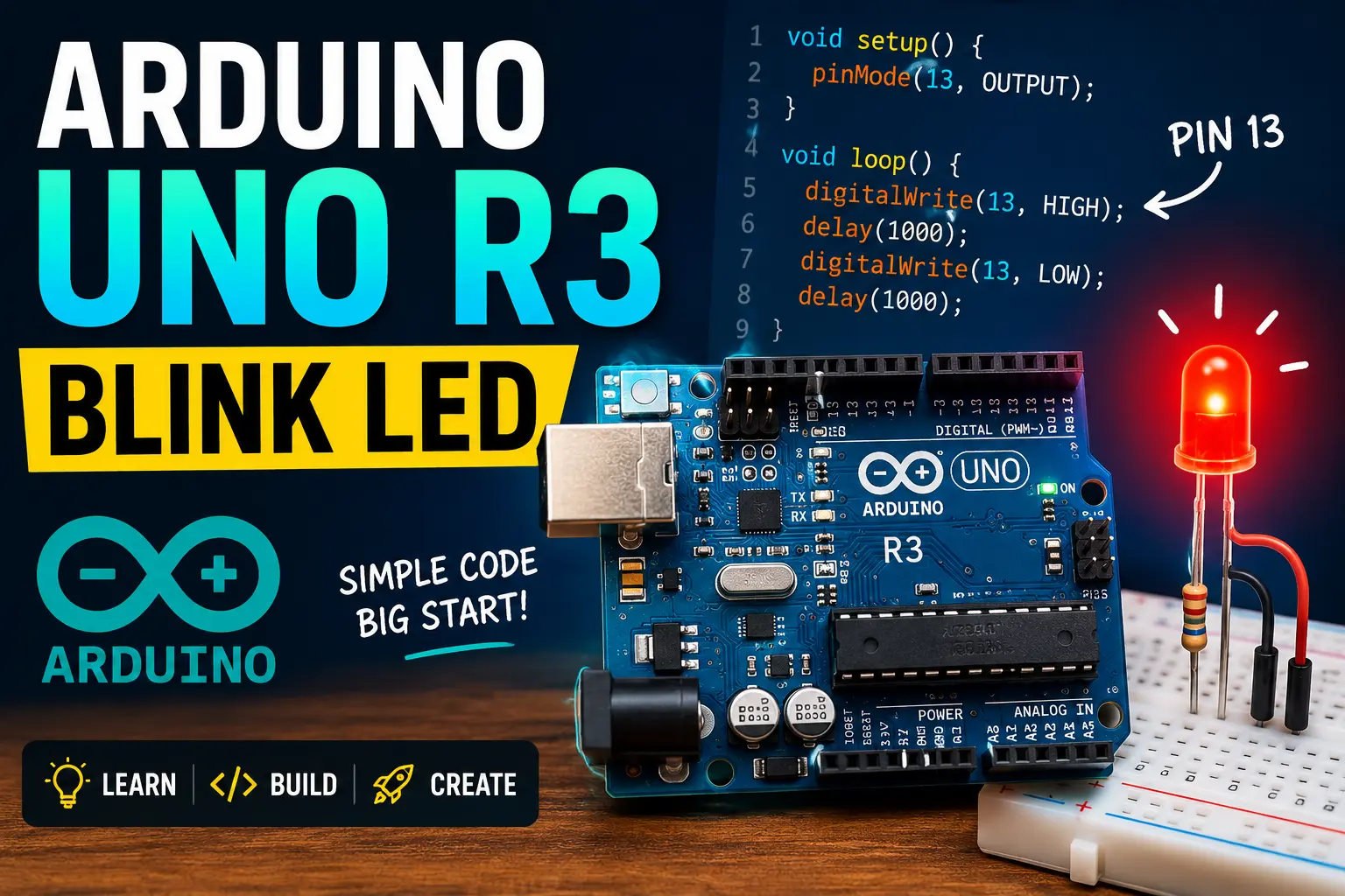
- Built-in LED on pin 13: there is a small SMD LED connected to digital pin 13 through a current-limiting resistor already on the board. This is what the default
Blinkexample uses — but wiring an external LED is more educational and that is what we will do here.
💡 Tip
The 3.3V pin is limited to 150 mA and shares the regulator with the board itself. If you attach a 3.3V module that draws more, the voltage drops and the board becomes unstable. For hungry 3.3V peripherals, use a dedicated AMS1117-3.3 regulator off the 5V rail.
Installing the Arduino IDE
Download Arduino IDE 2 from arduino.cc/en/software — it is free and runs on Windows, macOS, and Linux. The installer bundles the AVR toolchain, so no separate compiler setup is needed.
After installation:
- Plug the Uno into a USB port
- In the IDE, go to Tools → Board → Arduino AVR Boards → Arduino Uno
- Go to Tools → Port and select the COM port (Windows) or
/dev/ttyUSB0//dev/cu.usbmodemXXX(Linux/macOS) that appeared when you plugged the board in - Open File → Examples → 01.Basics → Blink and click Upload (→ arrow button)
If the built-in LED starts flashing once per second, the toolchain and USB driver are working correctly.
Components required
Why the Resistor?
A bare LED has almost no internal resistance. If you connect it directly between 5V and GND it pulls as much current as the wire can supply — within milliseconds the LED dies and the pin driver on the ATmega may be damaged too.
The forward voltage of a standard red LED is roughly 2.0V. The GPIO pin outputs 5V. Ohm's law tells us the resistor value needed to limit current to a safe 20 mA:
R = (V_supply - V_led) / I = (5.0 - 2.0) / 0.020 = 150 Ω
A 220 Ω resistor gives about 13 mA — the LED is slightly dimmer but the margin of safety is better, and the Arduino pin (rated 40 mA max, 20 mA recommended) is well within limits. For a blue or white LED (forward voltage ≈ 3.2V) use 100 Ω instead.
The resistor can go on either side of the LED — it does not matter electrically which leg it touches.
Wiring
Identify the LED polarity first. The longer leg is the anode (+); the shorter leg is the cathode (−). On a new LED the flat edge of the plastic dome is also on the cathode side.
- Insert the LED into the breadboard across the center gap
- Connect the anode (long leg) through the 220 Ω resistor to digital pin 9 on the Uno
- Connect the cathode (short leg) directly to any GND pin on the Uno
That is the complete circuit. Two wires and a resistor.
// ── Arduino Uno R3 — External LED Blink ──────────────────────────────────────
// Blinks an LED on pin 9 with a configurable period.
// Modify ON_MS and OFF_MS to change the flash pattern.
// ─────────────────────────────────────────────────────────────────────────────

#define LED_PIN   9       // Digital pin connected to LED anode (via 220Ω)
#define ON_MS    500      // How long the LED stays on  (milliseconds)
#define OFF_MS   500      // How long the LED stays off (milliseconds)

void setup() {
  // Tell the ATmega this pin should drive current (output mode)
  pinMode(LED_PIN, OUTPUT);

  // Optional: open Serial so you can watch the blink count in the monitor
  Serial.begin(9600);
  Serial.println("Blink sketch started");
}

void loop() {
  // HIGH drives the pin to 5V → current flows → LED lights up
  digitalWrite(LED_PIN, HIGH);
  Serial.println("LED ON");
  delay(ON_MS);

  // LOW pulls the pin to 0V → no current → LED off
  digitalWrite(LED_PIN, LOW);
  Serial.println("LED OFF");
  delay(OFF_MS);
}
Live simulation
Uploading and Verifying
- Paste the sketch into a new IDE window (or modify the example)
- Click the Verify tick button — the IDE should show
Done compiling - Click Upload arrow — the RX/TX LEDs on the board will flicker as code transfers
- Within two seconds of upload completing, the LED on pin 9 should start blinking
If you see avrdude: stk500_getsync() errors, the board is on the wrong COM port or the USB cable is charge-only (no data lines).
Steps
- 1Install Arduino IDE 2 from arduino.cc and plug in the Uno via USB
- 2Verify the board is detected: Tools → Port should show a new entry
- 3Upload the default Blink example to confirm the toolchain works
- 4Wire the external LED: anode → 220Ω → pin 9, cathode → GND
- 5Paste the sketch above, change LED_PIN to 9, and upload
- 6Watch the LED blink — open Serial Monitor (9600 baud) to see ON/OFF messages
- 7Try changing ON_MS to 100 and OFF_MS to 900 for a short flash pattern
Where to Go Next
Once the LED blinks reliably you have proven the entire development chain works — IDE, driver, USB bridge, flash memory, and GPIO. From here the natural next steps are:
- Push button: read
digitalRead()and toggle the LED with a button press - Potentiometer: use
analogRead()on A0 to vary LED brightness withanalogWrite()(PWM) - Morse code: encode your name as a sequence of ON_MS/OFF_MS delays
- Multiple LEDs: wire LEDs to pins 6, 7, 8, 9 and create a running-light animation in
loop()