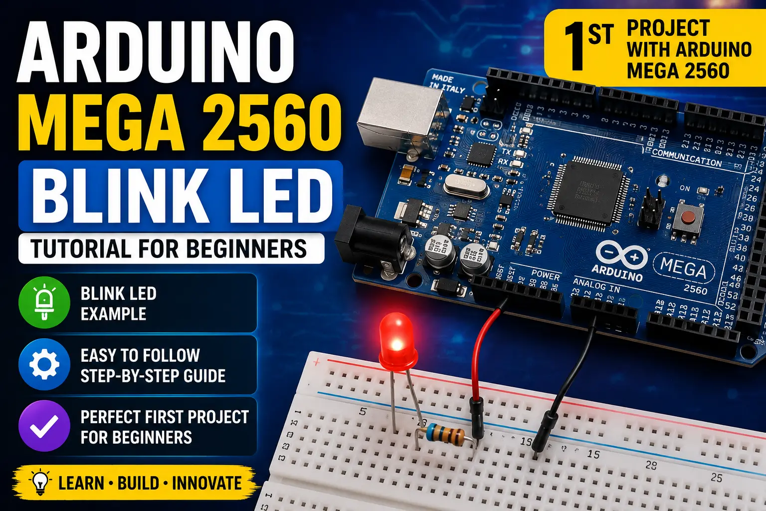
Arduino Mega 2560 Blink LED Tutorial for Beginners
First look at the Arduino Mega 2560: understand why it exists, map out its 54 digital pins and 16 analog channels, set up the IDE, and blink an external LED using a pin you would never have on an Uno.
The Mega vs the Uno — When Does the Extra Hardware Matter?
The Arduino Mega 2560 runs the same AVR architecture as the Uno but on a much bigger chip: the ATmega2560. The core differences that actually matter in practice:
| Feature | Uno R3 | Mega 2560 | |---------|--------|-----------| | Flash memory | 32 KB | 256 KB | | SRAM | 2 KB | 8 KB | | Digital I/O | 14 | 54 | | PWM pins | 6 | 15 | | Analog inputs | 6 | 16 | | Hardware UARTs | 1 | 4 | | I2C buses | 1 | 1 | | SPI buses | 1 | 1 |
The Uno is the right choice for 80% of projects. Reach for the Mega when you genuinely run out of pins or flash — large LED matrix projects, CNC controllers (GRBL + RAMPS), 3D printers (Marlin firmware), or anything that needs multiple independent serial ports simultaneously.
Board Layout
The Mega is physically larger (101.5 × 53.4 mm vs Uno's 68.6 × 53.4 mm) and has additional pin headers extending down both sides:
- Digital 0–13: same positions as Uno — compatible with most shields
- Digital 14–53: the extra pins, running down the sides
- PWM-capable pins: 2–13 and 44–46 (marked with ~)
- Analog A0–A15: on the right side header
- Four UART pairs: Serial (0/1), Serial1 (18/19), Serial2 (16/17), Serial3 (14/15)
- Power rail: same header as Uno — 3.3V, 5V, GND, VIN
One thing that catches people: the Mega uses a USB-B connector just like the Uno, but the USB-to-serial chip is the ATmega16U2 on R3 boards. The board is powered fine from USB.
💡 Tip
Mega shields are physically compatible with Uno shields as long as the shield only uses pins 0–13 and A0–A5. Some Uno shields block the extra Mega headers physically — check the shield dimensions before stacking.
Components required
Wiring — Three LEDs on Pins 22, 23, 24
We will use three of the Mega-only digital pins to make this distinct from the Uno exercise:
- LED 1 anode → 220 Ω → pin 22, cathode → GND
- LED 2 anode → 220 Ω → pin 23, cathode → GND
- LED 3 anode → 220 Ω → pin 24, cathode → GND
These pins sit on the right-side header that the Uno does not have. Any of pins 22–53 work identically for basic digital output.
// ── Arduino Mega 2560 — Three-LED Chase Pattern ──────────────────────────────
// Uses pins 22, 23, 24 — the "Mega-only" digital header.
// Demonstrates that all 54 digital pins behave identically for basic GPIO.
// ─────────────────────────────────────────────────────────────────────────────

const int LEDS[]   = {22, 23, 24};
const int NUM_LEDS = sizeof(LEDS) / sizeof(LEDS[0]);
const int STEP_MS  = 200;   // Time each LED stays lit

void setup() {
  for (int i = 0; i < NUM_LEDS; i++) {
    pinMode(LEDS[i], OUTPUT);
  }
  Serial.begin(9600);
  Serial.print("Arduino Mega 2560 — using ");
  Serial.print(NUM_LEDS);
  Serial.println(" LEDs on pins 22-24");
}

void loop() {
  // Forward chase: 22 → 23 → 24
  for (int i = 0; i < NUM_LEDS; i++) {
    digitalWrite(LEDS[i], HIGH);
    delay(STEP_MS);
    digitalWrite(LEDS[i], LOW);
  }

  // Reverse chase: 24 → 23 → 22
  for (int i = NUM_LEDS - 1; i >= 0; i--) {
    digitalWrite(LEDS[i], HIGH);
    delay(STEP_MS);
    digitalWrite(LEDS[i], LOW);
  }

  // All on briefly as a separator
  for (int i = 0; i < NUM_LEDS; i++) digitalWrite(LEDS[i], HIGH);
  delay(STEP_MS * 2);
  for (int i = 0; i < NUM_LEDS; i++) digitalWrite(LEDS[i], LOW);
  delay(STEP_MS);
}
IDE Setup for Mega
In Arduino IDE 2, the only change needed versus the Uno workflow is the board selection:
Tools → Board → Arduino AVR Boards → Arduino Mega or Mega 2560
Then set Tools → Processor → ATmega2560 (the 1280 variant is a much older, rarer board).
The port selection is the same process. Upload speed defaults to 115200 baud for the Mega, which is faster than the Uno's 115200 — uploads complete noticeably quicker because of the larger flash.
Steps
- 1Select board: Arduino Mega or Mega 2560 → Processor: ATmega2560
- 2Wire three LEDs through 220Ω resistors to pins 22, 23, 24
- 3Upload the chase sketch — LEDs should run forward and backward
- 4Open Serial Monitor at 9600 baud to confirm the startup message prints
- 5Try adding a 4th LED on pin 25 — extend the LEDS array and reupload
- 6Notice the upload is fast — 256 KB flash, but code transfer is quick at 115200 baud