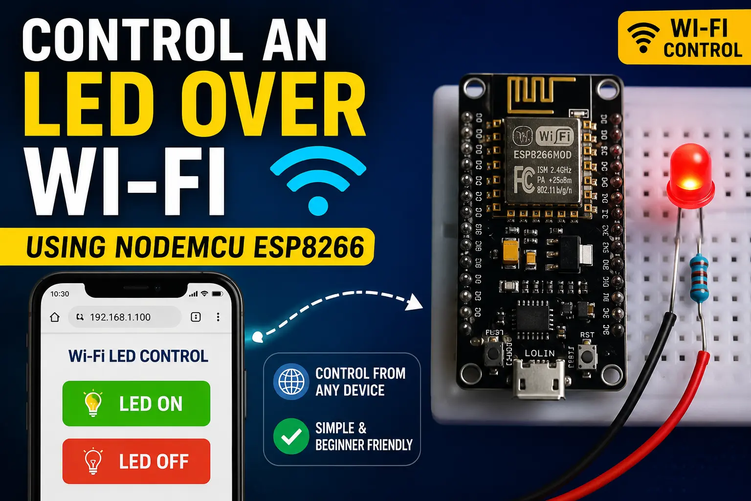
Control an LED Over Wi-Fi Using NodeMCU ESP8266
Full introduction to the NodeMCU ESP8266 v3 (LoLin) board: GPIO numbering oddity explained, 3.3V logic, CH340 driver, board manager setup, and a first blink using both the onboard LED and an external one — correctly.
NodeMCU ESP8266 — The WiFi Board That Started the IoT Craze
Before the ESP32 existed, the ESP8266 was the chip that put WiFi on a $2 module and changed what hobbyists could build. The NodeMCU v3 (also sold as LoLin) puts the ESP-12F module on a breadboard-friendly dev board with a CH340G USB-to-serial chip, micro-USB port, and 3.3V regulator — everything you need to start coding over USB.
Specs that matter:
- Tensilica L106 CPU at 80 MHz (overclockable to 160 MHz)
- 4 MB Flash, 80 KB of user SRAM
- 802.11 b/g/n WiFi — same capabilities as the ESP32 but single-core and no Bluetooth
- 11 usable GPIO pins (the ESP8266 has 17 but many are committed to flash and boot)
- 1 analog input (ADC on A0, 0–1V range — not 0–3.3V)
- 3.3V logic throughout
In 2025, the ESP32 costs only slightly more and is considerably more capable. The NodeMCU ESP8266 remains popular because millions of tutorials reference it and the CH340 driver situation is well-solved. If you already own one, it is an excellent learning board.
The GPIO Numbering Problem — D0 vs GPIO Numbers
This trips up nearly every NodeMCU beginner. The silkscreen on the board prints labels like D0, D1, D2...D8 but the Arduino digitalWrite() function expects GPIO numbers, which are different:
| Silkscreen Label | GPIO Number | Notes | |-----------------|-------------|-------| | D0 | GPIO 16 | No PWM, no interrupt | | D1 | GPIO 5 | Commonly SCL (I2C) | | D2 | GPIO 4 | Commonly SDA (I2C) | | D3 | GPIO 0 | Boot mode pin — pull-up required | | D4 | GPIO 2 | Onboard LED (active LOW), boot pin | | D5 | GPIO 14 | SPI CLK | | D6 | GPIO 12 | SPI MISO | | D7 | GPIO 13 | SPI MOSI | | D8 | GPIO 15 | Must be LOW at boot |
In Arduino IDE code you can either write the GPIO number directly (pinMode(4, OUTPUT)) or use the D2 macro which the ESP8266 board package defines as 4 (pinMode(D2, OUTPUT)). Both work — the macro form is more readable.
⚠️ Warning
The onboard LED (D4 / GPIO 2) is **active LOW**: `digitalWrite(D4, LOW)` turns it ON, `HIGH` turns it OFF. This is the opposite of most Arduino examples. The LED is also on a boot-strapping pin and will flicker during upload — this is normal.
ADC Caveat
The ESP8266's ADC (A0 pin) accepts 0 to 1.0V, not 0–3.3V like most microcontrollers. The NodeMCU v3 board includes a voltage divider on the A0 pin that scales the usable input range to 0–3.3V at the physical pin. If you use a bare ESP-12F module without the NodeMCU divider, the input must stay under 1V. Check your board's schematic if analog readings seem wrong.
Installing the ESP8266 Board Package
The ESP8266 needs a different board URL from the ESP32:
- Open File → Preferences
- In Additional boards manager URLs, add:
https://arduino.esp8266.com/stable/package_esp8266com_index.json - Tools → Board → Boards Manager → search esp8266 → install esp8266 by ESP8266 Community
- Select Tools → Board → ESP8266 Boards → NodeMCU 1.0 (ESP-12E Module)
- Set Tools → Upload Speed → 115200
The CH340G driver is the same one used by many cheap Arduino clones — if it is already installed from a previous project, you are set.
Components required
Wiring the External LED
We will use D5 (GPIO 14) — a clean output pin with no boot implications:
- LED anode → 330 Ω → D5 header pin on NodeMCU
- LED cathode → GND on NodeMCU
The board outputs 3.3V on GPIO pins. The 330 Ω resistor limits current to about 4 mA, which gives a visible glow. Swap to 150 Ω for a brighter result.
// ── NodeMCU ESP8266 v3 — Dual LED Blink ──────────────────────────────────────
// Blinks the onboard LED (D4 / GPIO2, active-LOW) and an external LED on D5.
// Shows both pin-label and GPIO-number styles — either works.
// ─────────────────────────────────────────────────────────────────────────────

// Using D-label macros (defined by esp8266 board package)
#define ONBOARD_LED  D4    // GPIO 2 — active LOW
#define EXT_LED      D5    // GPIO 14 — active HIGH

void setup() {
  Serial.begin(115200);
  delay(100);  // Let serial settle

  pinMode(ONBOARD_LED, OUTPUT);
  pinMode(EXT_LED, OUTPUT);

  // Start with both off
  digitalWrite(ONBOARD_LED, HIGH);  // HIGH = off for active-LOW LED
  digitalWrite(EXT_LED, LOW);

  Serial.println("
────────────────────────────────");
  Serial.println("NodeMCU ESP8266 — Dual LED Blink");
  Serial.printf("CPU: %d MHz  |  Free heap: %d B
",
                ESP.getCpuFreqMHz(), ESP.getFreeHeap());
  Serial.println("────────────────────────────────
");
}

void loop() {
  // Phase A: onboard LED on, external off
  digitalWrite(ONBOARD_LED, LOW);   // LOW = ON (active-LOW)
  digitalWrite(EXT_LED,     LOW);   // off
  Serial.println("Onboard ON / External OFF");
  delay(500);

  // Phase B: onboard off, external on
  digitalWrite(ONBOARD_LED, HIGH);  // HIGH = OFF
  digitalWrite(EXT_LED,     HIGH);  // HIGH = ON
  Serial.println("Onboard OFF / External ON");
  delay(500);

  // Phase C: both on briefly
  digitalWrite(ONBOARD_LED, LOW);
  digitalWrite(EXT_LED,     HIGH);
  Serial.println("Both ON");
  delay(200);

  // Reset
  digitalWrite(ONBOARD_LED, HIGH);
  digitalWrite(EXT_LED,     LOW);
  delay(300);
}
WiFi Hello World — One Step Further
Once the LED blinks you have confirmed the board and toolchain work. The natural next step for a WiFi-capable board is connecting to your network. Add this to setup() after the LED blink section:
#include <ESP8266WiFi.h>

WiFi.begin("YOUR_SSID", "YOUR_PASSWORD");
while (WiFi.status() != WL_CONNECTED) {
  delay(500);
  Serial.print(".");
}
Serial.println();
Serial.print("Connected — IP: ");
Serial.println(WiFi.localIP());
Once this prints an IP address, your NodeMCU is on the network and ready to fetch URLs, run a web server, or publish to an MQTT broker.
Steps
- 1Add the ESP8266 board manager URL in IDE preferences and install the package
- 2Select board: NodeMCU 1.0 (ESP-12E Module), upload speed: 115200
- 3Install CH340 driver if the COM port does not appear
- 4Wire the external LED through 330Ω to D5, cathode to GND
- 5Upload the sketch — NodeMCU should auto-reset and start without holding BOOT
- 6Open Serial Monitor at 115200 — note the inverted behaviour of the onboard LED
- 7Test WiFi connectivity by adding the WiFi snippet to setup()